
Aug 29, 2026pneumatic cylinder

How to Calculate Pneumatic Cylinder Bore Size for Industrial Automation

Learn how to calculate pneumatic cylinder bore size using load, air pressure, safety factor, friction and installation conditions
89728d90-0b13-4823-b1bd-022e1ec4a3a6
How to Calculate Pneumatic Cylinder Bore Size for Industrial Automation
Choosing the correct pneumatic cylinder bore is important for reliable machine operation. If the cylinder is too small, it may not move the load consistently. If it is unnecessarily large, it will consume more compressed air and increase system cost.
The selection process begins with the required output force.

1. Calculate the Required Cylinder Force

The basic relationship is:
Force = Pressure × Piston Area
For practical selection, pressure should be expressed in pascals and piston area in square metre. The calculated result is expressed in newtons.
For example, suppose an application requires 500 N of actual pushing force and the working pressure is 0.6 MPa. A theoretical calculation may suggest a relatively small cylinder. However, pneumatic systems experience pressure fluctuation, seal friction, mechanical resistance and other losses.
Therefore, the theoretical force should not be used as the final selection value.

2. Apply a Safety Factor

A safety factor helps the cylinder continue operating when actual conditions are less favourable than expected. For general horizontal pushing or clamping, a safety factor of approximately 1.3 to 1.5 is commonly considered. Vertical lifting, varying loads or high-friction mechanisms may require a larger margin.
If the required operating force is 500 N and a safety factor of 1.5 is applied:
Required theoretical force = 500 × 1.5 = 750 N
The cylinder should therefore provide at least 750 N at the available operating pressure.

3. Consider Extension and Retraction Forces

A double-acting cylinder does not produce the same force in both directions. During extension, pressure acts on the full piston area. During retraction, the piston rod reduces the effective area.
This means that retraction force is lower than extension force. If the application requires pulling rather than pushing, the rod area must be included in the calculation.
Always check both extension and retraction force when the cylinder performs work in both directions.

4. Evaluate the Application Conditions

Cylinder bore cannot be selected from load alone. Also consider:
  • Available air pressure
  • Horizontal or vertical installation
  • Load speed and acceleration
  • Guide friction
  • Stroke length
  • Operating frequency
  • Side load
  • Cushioning requirements
Pneumatic cylinders should not normally carry significant side loads. An external guide or linear bearing should support the load when lateral force is present.
Long-stroke cylinders also require attention to piston-rod buckling. A larger rod diameter or guided cylinder may be necessary even when the calculated thrust is sufficient.

5. Select the Nearest Standard Bore

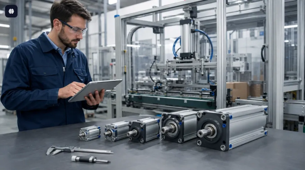
After calculating the minimum piston area, select the next larger standard bore. Common standard bores include 20, 25, 32, 40, 50, 63, 80 and 100 mm, depending on the cylinder series.
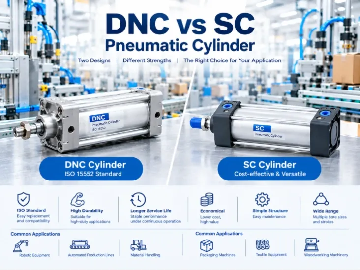
Compact CQ2B cylinders are suitable where installation space is limited. DNC or other ISO-profile cylinders are useful for standardized industrial machinery, while SC tie-rod cylinders are widely used in general automation.
Finally, confirm the mounting type, stroke, port size, sensor requirement and cushioning method. A properly selected cylinder provides sufficient force without excessive air consumption and delivers more stable long-term performance.


Read next

Aug 29, 2026pneumatic cylinder

How to Calculate Pneumatic Cylinder Bore Size for Industrial Automation

Learn how to calculate pneumatic cylinder bore size using load, air pressure, safety factor, friction and installation conditions

89728d90-0b13-4823-b1bd-022e1ec4a3a6
How to Calculate Pneumatic Cylinder Bore Size for Industrial Automation
Choosing the correct pneumatic cylinder bore is important for reliable machine operation. If the cylinder is too small, it may not move the load consistently. If it is unnecessarily large, it will consume more compressed air and increase system cost.
The selection process begins with the required output force.

1. Calculate the Required Cylinder Force

The basic relationship is:
Force = Pressure × Piston Area
For practical selection, pressure should be expressed in pascals and piston area in square metre. The calculated result is expressed in newtons.
For example, suppose an application requires 500 N of actual pushing force and the working pressure is 0.6 MPa. A theoretical calculation may suggest a relatively small cylinder. However, pneumatic systems experience pressure fluctuation, seal friction, mechanical resistance and other losses.
Therefore, the theoretical force should not be used as the final selection value.

2. Apply a Safety Factor

A safety factor helps the cylinder continue operating when actual conditions are less favourable than expected. For general horizontal pushing or clamping, a safety factor of approximately 1.3 to 1.5 is commonly considered. Vertical lifting, varying loads or high-friction mechanisms may require a larger margin.
If the required operating force is 500 N and a safety factor of 1.5 is applied:
Required theoretical force = 500 × 1.5 = 750 N
The cylinder should therefore provide at least 750 N at the available operating pressure.

3. Consider Extension and Retraction Forces

A double-acting cylinder does not produce the same force in both directions. During extension, pressure acts on the full piston area. During retraction, the piston rod reduces the effective area.
This means that retraction force is lower than extension force. If the application requires pulling rather than pushing, the rod area must be included in the calculation.
Always check both extension and retraction force when the cylinder performs work in both directions.

4. Evaluate the Application Conditions

Cylinder bore cannot be selected from load alone. Also consider:
  • Available air pressure
  • Horizontal or vertical installation
  • Load speed and acceleration
  • Guide friction
  • Stroke length
  • Operating frequency
  • Side load
  • Cushioning requirements
Pneumatic cylinders should not normally carry significant side loads. An external guide or linear bearing should support the load when lateral force is present.
Long-stroke cylinders also require attention to piston-rod buckling. A larger rod diameter or guided cylinder may be necessary even when the calculated thrust is sufficient.

5. Select the Nearest Standard Bore

After calculating the minimum piston area, select the next larger standard bore. Common standard bores include 20, 25, 32, 40, 50, 63, 80 and 100 mm, depending on the cylinder series.
Compact CQ2B cylinders are suitable where installation space is limited. DNC or other ISO-profile cylinders are useful for standardized industrial machinery, while SC tie-rod cylinders are widely used in general automation.
Finally, confirm the mounting type, stroke, port size, sensor requirement and cushioning method. A properly selected cylinder provides sufficient force without excessive air consumption and delivers more stable long-term performance.

Aug 29, 2026pneumatic cylinder

How to Calculate Pneumatic Cylinder Bore Size for Industrial Automation

Learn how to calculate pneumatic cylinder bore size using load, air pressure, safety factor, friction and installation conditions

89728d90-0b13-4823-b1bd-022e1ec4a3a6
How to Calculate Pneumatic Cylinder Bore Size for Industrial Automation
Choosing the correct pneumatic cylinder bore is important for reliable machine operation. If the cylinder is too small, it may not move the load consistently. If it is unnecessarily large, it will consume more compressed air and increase system cost.
The selection process begins with the required output force.

1. Calculate the Required Cylinder Force

The basic relationship is:
Force = Pressure × Piston Area
For practical selection, pressure should be expressed in pascals and piston area in square metre. The calculated result is expressed in newtons.
For example, suppose an application requires 500 N of actual pushing force and the working pressure is 0.6 MPa. A theoretical calculation may suggest a relatively small cylinder. However, pneumatic systems experience pressure fluctuation, seal friction, mechanical resistance and other losses.
Therefore, the theoretical force should not be used as the final selection value.

2. Apply a Safety Factor

A safety factor helps the cylinder continue operating when actual conditions are less favourable than expected. For general horizontal pushing or clamping, a safety factor of approximately 1.3 to 1.5 is commonly considered. Vertical lifting, varying loads or high-friction mechanisms may require a larger margin.
If the required operating force is 500 N and a safety factor of 1.5 is applied:
Required theoretical force = 500 × 1.5 = 750 N
The cylinder should therefore provide at least 750 N at the available operating pressure.

3. Consider Extension and Retraction Forces

A double-acting cylinder does not produce the same force in both directions. During extension, pressure acts on the full piston area. During retraction, the piston rod reduces the effective area.
This means that retraction force is lower than extension force. If the application requires pulling rather than pushing, the rod area must be included in the calculation.
Always check both extension and retraction force when the cylinder performs work in both directions.

4. Evaluate the Application Conditions

Cylinder bore cannot be selected from load alone. Also consider:
  • Available air pressure
  • Horizontal or vertical installation
  • Load speed and acceleration
  • Guide friction
  • Stroke length
  • Operating frequency
  • Side load
  • Cushioning requirements
Pneumatic cylinders should not normally carry significant side loads. An external guide or linear bearing should support the load when lateral force is present.
Long-stroke cylinders also require attention to piston-rod buckling. A larger rod diameter or guided cylinder may be necessary even when the calculated thrust is sufficient.

5. Select the Nearest Standard Bore

After calculating the minimum piston area, select the next larger standard bore. Common standard bores include 20, 25, 32, 40, 50, 63, 80 and 100 mm, depending on the cylinder series.
Compact CQ2B cylinders are suitable where installation space is limited. DNC or other ISO-profile cylinders are useful for standardized industrial machinery, while SC tie-rod cylinders are widely used in general automation.
Finally, confirm the mounting type, stroke, port size, sensor requirement and cushioning method. A properly selected cylinder provides sufficient force without excessive air consumption and delivers more stable long-term performance.


Recommended articles

Guides visitors may want next

Helpful guides, field notes, and stories for choosing with more context.