
Aug 20, 2026pneumatic fittings

How to Build a Reliable Pneumatic System for CNC Equipment

Building a reliable pneumatic system requires more than selecting individual components. Air quality, pressure, flow capacity, circuit design, installation, control logic, safety, and preventive maint
b075b6dc-0375-4a49-87b1-2400d6d426ec

How to Build a Reliable Pneumatic System for CNC Equipment

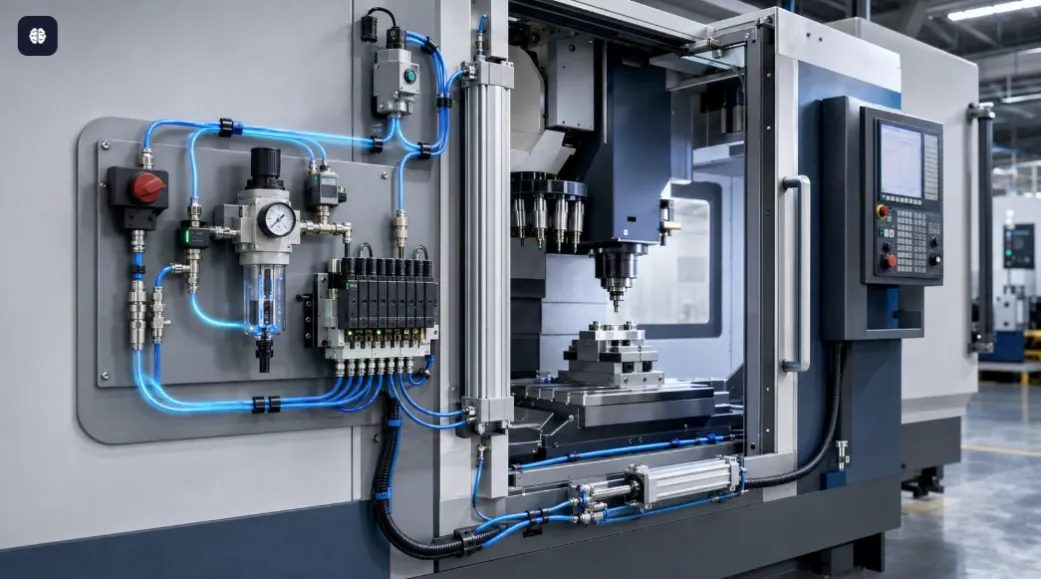
Pneumatic systems perform many important functions in CNC equipment, including tool changing, workpiece clamping, spindle sealing, door operation, component positioning, chip removal, and air-blow cleaning.
Although these functions may appear simple, an unreliable pneumatic system can stop the entire CNC machine. Low pressure, contaminated air, undersized valves, leaking fittings, or incorrectly installed cylinders may cause incomplete tool changes, unstable clamping, positioning errors, and unexpected downtime.
Building a reliable pneumatic system requires more than selecting individual components. Air quality, pressure, flow capacity, circuit design, installation, control logic, safety, and preventive maintenance must all be considered as one complete system.

1. Identify Every Pneumatic Function

The design process should begin with a complete list of pneumatic functions on the CNC machine.
Common applications include:
  • Automatic tool changer operation
  • Workpiece clamping and unclamping
  • Chuck or collet control
  • Spindle taper cleaning
  • Spindle air sealing
  • Tool-detection air circuits
  • Automatic machine-door operation
  • Fixture positioning
  • Pallet-changing systems
  • Chip and coolant removal
  • Air-blow cleaning
  • Lubrication-system control
  • Pneumatic counterbalance systems
  • Dust protection
  • Part ejection and transfer
For each function, record:
  • Required force
  • Stroke or movement
  • Operating pressure
  • Air consumption
  • Cycle frequency
  • Required operating speed
  • Acceptable response time
  • Duty cycle
  • Safety condition during pressure loss
  • Environmental conditions
This information provides the basis for selecting cylinders, valves, tubing, fittings, and air-treatment equipment.

2. Start with Clean, Dry Compressed Air

Compressed-air quality is one of the most important factors affecting CNC equipment reliability.
Untreated air may contain:
  • Water vapor
  • Condensed moisture
  • Compressor oil
  • Rust
  • Pipe scale
  • Dust
  • Metal particles
  • Microorganisms
  • Other industrial contaminants
These contaminants can damage cylinder seals, block small valve passages, cause solenoid valves to stick, and interfere with spindle sealing or tool-detection functions.
A typical air-preparation arrangement may include:
Compressed-Air Supply → Shut-Off Valve → Water Separator → Air Filter → Pressure Regulator → Fine Filter, if required → Machine Pneumatic Circuit

Standard Air Filtration

A general-purpose filter, such as a 40 μm pneumatic air filter, can remove larger solid particles and separate condensed moisture.
This filtration level may be suitable for general cylinder and valve circuits.

Fine Filtration

Critical circuits may require finer filtration. A 5 μm filter or coalescing filter may be considered for:
  • Spindle air sealing
  • Tool-detection circuits
  • Precision pneumatic measurement
  • Small-passage solenoid valves
  • Sensitive control components
A standard particulate filter does not remove all oil aerosols or water vapor. Where very clean air is required, additional coalescing filters, activated-carbon filters, membrane dryers, or refrigerated dryers may be necessary.

Moisture Control

Water inside a CNC pneumatic system may cause:
  • Corrosion
  • Valve sticking
  • Seal deterioration
  • Frozen drain mechanisms
  • Contaminated spindle air
  • Unstable pressure signals
Filters should be installed vertically with the bowl facing downward. Condensate must be drained before it reaches the filter element.
Automatic drains are recommended for continuously operating machines or installations where manual drainage may be forgotten.

3. Select the Correct Operating Pressure

Many CNC pneumatic circuits operate within a general pressure range of approximately 0.4-0.7 MPa, but the correct value depends on the machine and component specifications.
Using excessive pressure may result in:
  • Hard cylinder impact
  • Premature seal wear
  • Higher air consumption
  • Increased noise
  • Damaged fixtures
  • Excessive clamping force
  • Increased stress on tubing and fittings
Pressure that is too low may cause:
  • Incomplete tool changes
  • Insufficient clamping force
  • Slow cylinder movement
  • Chuck-release failure
  • Door-operation faults
  • Unstable spindle sealing
  • Low-pressure alarms
The pressure regulator should be set to the lowest value that allows every pneumatic function to operate reliably under peak production conditions.

Use Separate Pressure Zones

Not every circuit needs the same pressure. A CNC machine may benefit from separate regulated pressure zones for:
  • Tool-changing mechanisms
  • Clamping circuits
  • Door cylinders
  • Air-blow circuits
  • Spindle sealing
  • Precision sensing circuits
Separate regulators prevent high-consumption functions from disturbing pressure-sensitive circuits.
For example, a high-flow chip-blowing circuit should not cause the spindle-seal pressure to fall below its required level.

4. Calculate the Required Cylinder Force

A pneumatic cylinder must provide enough force to move the load under actual operating conditions.
The theoretical extension force can be estimated using:
Extension Force = Operating Pressure × Piston Area
For the return stroke:
Return Force = Operating Pressure × Annular Area
The annular area is the piston area minus the piston-rod area.
The actual available force is lower than the theoretical value because of:
  • Seal friction
  • Mechanical resistance
  • Pressure loss
  • Load variation
  • Misalignment
  • Acceleration
  • Safety requirements
A suitable safety factor should therefore be included. The cylinder should not be selected to operate continuously at its maximum theoretical output.
For vertical loads, clamping systems, tool changers, and safety-critical functions, designers must also consider gravity, vibration, inertia, and the consequences of pressure loss.

5. Choose the Correct Cylinder Type

Different CNC applications require different pneumatic cylinder designs.

Standard Cylinders

Standard cylinders are suitable for general linear movement where sufficient installation space is available.

Compact Cylinders

Compact cylinders are useful inside restricted machine enclosures and tool-changing mechanisms.

Guided Cylinders

Guided cylinders are suitable when the actuator must resist side loads, maintain orientation, or provide more accurate linear movement.

Rodless Cylinders

Rodless cylinders can provide long strokes in limited installation space, such as automatic-door applications.

Rotary Actuators

Rotary pneumatic actuators may be used for component turning, fixture indexing, or mechanical switching.

Clamping Cylinders

Dedicated clamping cylinders are designed for fixture and workholding applications where controlled, repeatable force is important.
The piston rod of a standard cylinder should transmit axial force only. External guide rails or guided-cylinder designs should support radial loads and moments.

6. Prevent Side Loading and Misalignment

Cylinder misalignment is a common cause of premature failure.
When the piston rod is forced sideways, it increases wear on the rod seal and bearing. This may cause:
  • Scratched piston rods
  • Bent rods
  • Uneven seal wear
  • External air leakage
  • Increased friction
  • Jerky movement
  • Shortened cylinder life
The cylinder, load, and guide mechanism should be accurately aligned. A floating joint can compensate for small installation errors between the cylinder rod and the driven mechanism.
Heavy components should be supported by linear guide rails rather than directly by the piston rod.

7. Select Valves According to Function and Flow

Solenoid valves control the direction, start, and stop of compressed air.
Common configurations include:
  • 3/2-way valves: Typically used for single-acting cylinders, pilot signals, and air-blow circuits
  • 5/2-way valves: Commonly used for double-acting cylinders
  • 5/3-way valves: Used when a double-acting actuator requires a defined center condition
  • 2/2-way valves: Used for simple air-supply isolation or on/off control
Valve selection should consider:
  • Valve function
  • Required flow
  • Port size
  • Operating pressure
  • Response time
  • Coil voltage
  • Electrical connection
  • Manual override
  • Environmental protection
  • Required fail-safe position
A valve should not be selected only by thread size. Its internal flow capacity must be sufficient for the cylinder bore, stroke, speed, and operating frequency.
An undersized valve can cause slow cylinder movement and excessive pressure drop, even if the inlet pressure appears correct.

8. Confirm Coil Voltage and Electrical Compatibility

The solenoid-valve coil voltage must match the CNC machine’s electrical control system.
Common options include:
  • 12 V DC
  • 24 V DC
  • 24 V AC
  • 110 V AC
  • 220 V AC
Industrial CNC equipment commonly uses 24 V DC control signals, but the actual voltage must always be confirmed from the machine design.
Using the wrong coil voltage can cause:
  • Failure to switch
  • Unstable operation
  • Excessive coil temperature
  • Coil burnout
  • PLC output damage
The electrical connector should also be suitable for the environment. Consider exposure to coolant, oil mist, metal chips, vibration, and washdown.

9. Size Tubing and Fittings for Peak Flow

Tubing that is too small can restrict airflow and cause a significant pressure drop during rapid cylinder movement.
Tube selection should consider:
  • Cylinder bore
  • Stroke
  • Required speed
  • Tube length
  • Valve flow
  • Number of fittings
  • Operating pressure
  • Simultaneous air consumption
Larger tubing may be required for:
  • High-speed tool changers
  • Large clamping cylinders
  • Pneumatic chucks
  • Automatic doors
  • High-volume air-blow circuits
Shorter, more direct tube routes generally improve response time and reduce pressure loss.

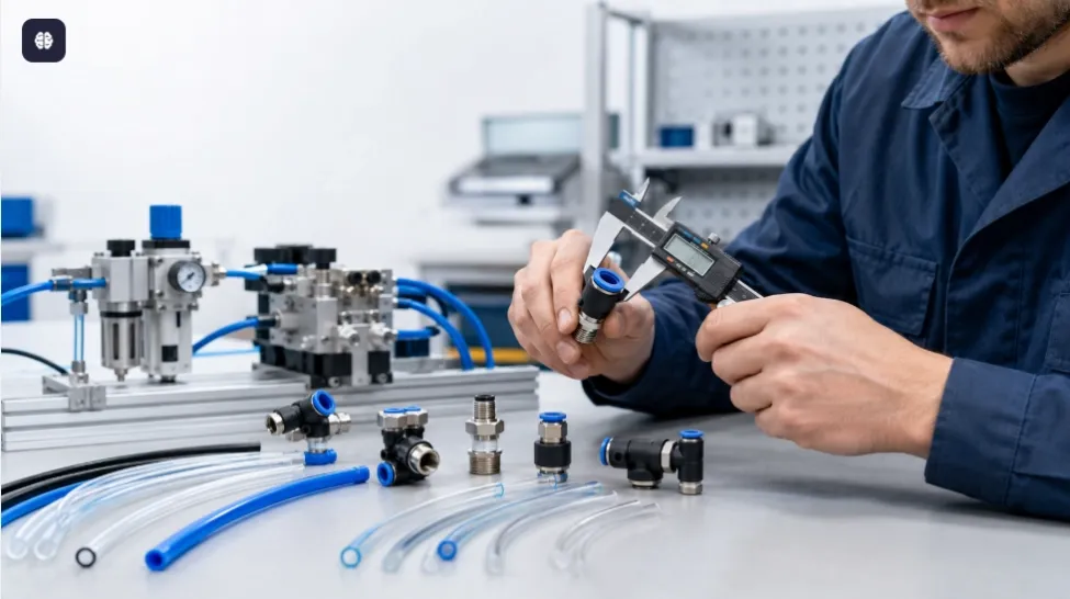
Use Reliable Pneumatic Fittings

Push-in fittings should:
  • Match the tube outside diameter
  • Use the correct thread standard
  • Provide secure tube retention
  • Have consistent sealing surfaces
  • Resist machine vibration
  • Be suitable for the operating pressure
Common pneumatic thread standards include G, PT, and NPT. These threads are not always interchangeable.
The selected thread must match the valve, cylinder, regulator, or manifold port.

10. Route Pneumatic Tubing Correctly

Correct tube routing improves reliability and simplifies maintenance.
Pneumatic tubes should be:
  • Cut squarely with a proper tube cutter
  • Inserted completely into push-in fittings
  • Protected from sharp metal edges
  • Kept away from hot surfaces
  • Separated from moving machine components
  • Protected from cutting chips
  • Secured without being crushed
  • Installed with sufficient bending radius
  • Given enough length for machine movement and maintenance
Avoid long unsupported tube sections and excessive tension near fittings.
Color-coded tubing can make CNC pneumatic circuits easier to identify. Different colors may be assigned to the main air supply, clamping circuits, tool-changing circuits, exhaust pilots, and auxiliary functions.

11. Control Cylinder Speed Correctly

Cylinder speed should normally be controlled with flow-control valves.
In many applications, meter-out control provides smoother movement because it restricts the exhaust airflow leaving the cylinder.
Proper speed adjustment helps prevent:
  • Hard end-of-stroke impact
  • Machine vibration
  • Tool-changer shock
  • Fixture damage
  • Unstable movement
  • Premature cylinder wear
Speed controllers should be installed close to the cylinder ports whenever practical.
Adjustment should begin at a low speed and increase gradually until the required cycle time is achieved without excessive impact.

12. Control End-of-Stroke Energy

A pneumatic cylinder moving a heavy load can create significant impact energy at the end of its stroke.
Repeated impact may damage:
  • Cylinder pistons
  • End covers
  • Mounting brackets
  • Guide mechanisms
  • Tool-changing arms
  • Machine fixtures
  • Sensors
  • Connected components
Depending on load, speed, and frequency, use:
  • Built-in cylinder cushioning
  • Adjustable air cushions
  • External shock absorbers
  • Mechanical stops
  • Deceleration circuits
  • Proportional control, where required
Mechanical stops should absorb structural load when appropriate rather than forcing the cylinder to carry all stopping energy.

13. Use Sensors to Confirm Actuator Position

CNC machine control should not assume that a pneumatic movement has been completed only because a valve has been energized.
Position sensors can confirm:
  • Cylinder extended
  • Cylinder retracted
  • Tool clamped
  • Tool released
  • Door open
  • Door closed
  • Fixture engaged
  • Fixture disengaged
  • Pallet positioned
The CNC or PLC program should verify the expected sensor signal within a defined time.
If the signal is not received, the machine should stop the sequence and generate an appropriate alarm rather than continuing with an incomplete operation.
This is particularly important for automatic tool-changing and workholding systems.

14. Monitor Pressure at Critical Points

A pressure gauge at the machine inlet provides basic information, but it may not reveal pressure loss inside an individual circuit.
Critical CNC functions may require:
  • Local pressure gauges
  • Pressure switches
  • Electronic pressure sensors
  • Vacuum switches
  • Differential-pressure monitoring
Pressure monitoring is especially important for:
  • Workpiece clamping
  • Pneumatic chuck operation
  • Tool clamping and release
  • Spindle sealing
  • Vacuum gripping
  • Safety-related holding circuits
A pressure switch can prevent machine operation when the available pressure is below the required level.
However, a pressure signal alone does not always prove that a workpiece or tool is correctly clamped. Position or part-presence sensing may also be required.

15. Separate High-Consumption Circuits

Air-blow nozzles can consume much more compressed air than cylinders and pilot valves.
If a large blow-off circuit shares an undersized supply line with clamping or spindle-sealing circuits, activating the nozzle may cause a temporary pressure drop.
This can lead to:
  • Tool-change alarms
  • Reduced clamping force
  • Spindle contamination
  • Slow cylinder response
  • Unstable process operation
High-consumption circuits should use:
  • Separate branch lines
  • Dedicated regulators
  • Properly sized valves
  • Larger tubing
  • Local air receivers, where appropriate
  • Energy-efficient nozzles
  • Timed air-blow control
Air-blow duration should be limited to the time required by the process.

16. Design for Safe Pressure Loss

A reliable system must consider what happens when electrical power or compressed air is lost.
Potential risks include:
  • A vertical load falling
  • A workpiece becoming unclamped
  • A tool being released
  • A door moving unexpectedly
  • Stored pressure causing delayed movement
  • An actuator restarting when air returns
Depending on the risk assessment, the circuit may require:
  • Pilot-operated check valves
  • Rod-locking cylinders
  • Mechanical locking devices
  • Safety-rated dump valves
  • Soft-start valves
  • Pressure switches
  • Redundant control
  • Controlled exhaust
  • Energy-isolation devices
Compressed air should not be treated as the sole means of supporting a suspended load. Mechanical protection should be used where unexpected movement could cause injury or equipment damage.

17. Install a Shut-Off and Soft-Start Valve

The machine should have an accessible compressed-air isolation valve for maintenance and emergency energy control.
A lockable shut-off valve allows the pneumatic supply to be isolated during service.
A soft-start valve can introduce pressure gradually when the system is restarted. This helps reduce sudden cylinder movement, hose movement, and mechanical shock.
Before maintenance, the air supply must be shut off and residual pressure safely discharged.
Technicians should verify that stored pneumatic energy has been released before disconnecting any component.

18. Control Exhaust Air

Exhaust air can create excessive noise and may spread oil mist, dust, or coolant contamination inside the CNC enclosure.
Pneumatic silencers can reduce exhaust noise, but they must be sized correctly.
An undersized or blocked silencer may:
  • Restrict exhaust flow
  • Reduce cylinder speed
  • Increase back pressure
  • Cause incomplete actuator movement
  • Extend machine cycle time
Silencers should be inspected regularly and replaced when contaminated.
Where clean machine interiors are important, exhaust air may be piped to a suitable collection or discharge location.

19. Consider the CNC Operating Environment

CNC equipment often exposes pneumatic components to demanding conditions, including:
  • Metal chips
  • Cutting fluid
  • Oil mist
  • Coolant spray
  • High humidity
  • Vibration
  • Heat
  • Abrasive dust
  • Repeated machine-door movement
Components should be selected and positioned to reduce direct exposure.
Recommended measures include:
  • Protective covers
  • Sealed electrical connectors
  • Corrosion-resistant fittings
  • Protected sensor cables
  • Abrasion-resistant tubing
  • Rod boots or scrapers
  • Remote valve manifolds
  • Enclosures for sensitive components
Polycarbonate filter bowls should be protected from incompatible solvents and chemicals. A bowl guard or suitable alternative material may be required in severe environments.

20. Minimize Air Leakage

Compressed-air leakage wastes energy and reduces the pressure available for machine operation.
Common leakage points include:
  • Push-in fittings
  • Damaged tubing
  • Solenoid valve seals
  • Cylinder rod seals
  • Threaded connections
  • Drain valves
  • Pressure gauges
  • Manifold gaskets
Leakage can be reduced by:
  • Cutting tubing squarely
  • Fully inserting tubing into fittings
  • Using the correct thread type
  • Applying sealant carefully
  • Replacing scratched tube ends
  • Inspecting seals regularly
  • Testing the system under pressure
  • Repairing small leaks before they grow
A machine that leaks while idle should be inspected instead of relying on the compressor to compensate continuously.

21. Make the System Easy to Maintain

Maintenance access should be considered during the design stage.
Technicians should be able to:
  • Read pressure gauges
  • Adjust regulators
  • Drain filter bowls
  • Replace filter elements
  • Access manual valve overrides
  • Disconnect valve plugs
  • Replace tubing
  • Inspect cylinders
  • Clean silencers
  • Test pressure switches
Components should be clearly labeled, and tubing should be organized according to the pneumatic schematic.
The machine documentation should include:
  • Pneumatic circuit diagram
  • Component model numbers
  • Pressure settings
  • Tube sizes
  • Valve voltage
  • Sensor locations
  • Spare-parts list
  • Maintenance intervals
  • Troubleshooting procedures

Recommended CNC Pneumatic System Layout

A practical CNC pneumatic system may include:
  1. Main compressed-air supply
  1. Lockable shut-off valve
  1. Soft-start or dump valve
  1. Water separator
  1. Main air filter
  1. Pressure regulator
  1. Pressure gauge and low-pressure switch
  1. Branch manifold
  1. Separate regulators for critical circuits
  1. Solenoid valve manifold
  1. Flow-control valves
  1. Pneumatic cylinders and actuators
  1. Position sensors
  1. Silencers or exhaust piping
The exact arrangement depends on the machine functions, safety requirements, air quality, and operating environment.

Component Selection Checklist

Component
Key Selection Factors
Air filter
Flow, filtration precision, drain type and bowl material
Pressure regulator
Inlet pressure, outlet range, flow and port size
Shut-off valve
Flow capacity, exhaust function and lockability
Solenoid valve
Ways, positions, flow, pressure, voltage and fail-safe state
Cylinder
Force, bore, stroke, speed, mounting and side load
Flow controller
Tube size, thread and required adjustment range
Tubing
Inside diameter, outside diameter, pressure, temperature and flexibility
Pneumatic fitting
Tube size, thread standard, sealing and retention
Pressure switch
Pressure range, accuracy, output and electrical compatibility
Silencer
Thread, exhaust flow and contamination resistance
Manifold
Number of stations, valve compatibility and total flow
Sensor
Detection position, electrical output and environmental protection

Preventive Maintenance Schedule

Daily or Weekly

  • Check the main operating pressure.
  • Drain accumulated condensate.
  • Listen for obvious air leakage.
  • Observe cylinder speed and movement.
  • Check for low-pressure alarms.
  • Inspect exposed tubing for damage.

Monthly

  • Inspect filters and filter bowls.
  • Check regulator settings.
  • Test pressure switches.
  • Inspect cylinder rods and seals.
  • Check valve connectors.
  • Examine tubing near moving components.
  • Inspect silencers for blockage.
  • Confirm sensor operation.

Periodically

  • Replace contaminated filter elements.
  • Repair air leaks.
  • Inspect valve switching performance.
  • Check cylinder alignment.
  • Test safety-related pneumatic functions.
  • Verify clamping and tool-changing pressure.
  • Review pressure drop during peak operation.
  • Update maintenance records.
Maintenance intervals should be based on actual operating hours, cycle count, air quality, environmental conditions, and machine importance.

Common Problems and Solutions

Problem
Possible Cause
Recommended Solution
Cylinder moves slowly
Low pressure or restricted flow
Check regulator, filter, tubing and valve sizing
Tool change is incomplete
Insufficient pressure or actuator fault
Verify pressure, sensors, cylinder and valve operation
Pressure drops during air blow
Shared supply is undersized
Separate the circuit or increase flow capacity
Solenoid valve sticks
Contaminated compressed air
Improve filtration and inspect the valve
Cylinder leaks
Worn seals or damaged rod
Repair the cylinder and correct alignment
Movement is jerky
Poor speed adjustment or side load
Adjust flow controls and inspect the guide mechanism
Filter fills quickly
Excessive moisture in the supply
Improve drying and use automatic drainage
Regulator pressure is unstable
Incorrect sizing or contamination
Inspect the filter and select a suitable regulator
Exhaust noise increases
Damaged or missing silencer
Install or replace the silencer
Repeated tube failure
Heat, abrasion or excessive bending
Reroute and protect the tubing
Coil overheats
Incorrect voltage
Verify the control voltage and coil specification
CNC reports low pressure
Supply shortage or large leakage
Check compressor capacity and perform a leak test

Final Commissioning Checklist

Before putting the CNC pneumatic system into production, confirm that:
  • All components match the design specifications.
  • The airflow direction is correct.
  • The system has been flushed before connection.
  • The air filter and drain operate correctly.
  • The regulator is set to the required pressure.
  • Pressure remains stable during peak consumption.
  • Tubing and fittings do not leak.
  • Cylinders are correctly aligned.
  • Flow-control valves are adjusted.
  • End-of-stroke impact is acceptable.
  • All position sensors operate correctly.
  • Solenoid valve voltages match the control system.
  • Manual overrides return to their normal condition.
  • Safety circuits respond correctly to pressure loss.
  • Residual energy can be isolated and exhausted safely.
  • Pneumatic drawings and component lists are complete.

Conclusion

A reliable CNC pneumatic system depends on correct air preparation, pressure control, airflow capacity, component selection, circuit design, and maintenance.
Clean and dry compressed air protects valves and cylinders. Properly sized regulators, valves, tubes, and fittings prevent pressure loss. Correct cylinder alignment and speed control reduce mechanical wear. Pressure and position sensors help the control system confirm that critical operations have been completed safely.
The best results come from designing the pneumatic circuit as a complete system rather than selecting each component independently.
A well-designed system can reduce CNC downtime, improve tool-changing reliability, maintain consistent clamping force, lower compressed-air consumption, and extend the service life of pneumatic components.

Read next

Aug 20, 2026pneumatic fittings

How to Build a Reliable Pneumatic System for CNC Equipment

Building a reliable pneumatic system requires more than selecting individual components. Air quality, pressure, flow capacity, circuit design, installation, control logic, safety, and preventive maint

b075b6dc-0375-4a49-87b1-2400d6d426ec

How to Build a Reliable Pneumatic System for CNC Equipment

Pneumatic systems perform many important functions in CNC equipment, including tool changing, workpiece clamping, spindle sealing, door operation, component positioning, chip removal, and air-blow cleaning.
Although these functions may appear simple, an unreliable pneumatic system can stop the entire CNC machine. Low pressure, contaminated air, undersized valves, leaking fittings, or incorrectly installed cylinders may cause incomplete tool changes, unstable clamping, positioning errors, and unexpected downtime.
Building a reliable pneumatic system requires more than selecting individual components. Air quality, pressure, flow capacity, circuit design, installation, control logic, safety, and preventive maintenance must all be considered as one complete system.

1. Identify Every Pneumatic Function

The design process should begin with a complete list of pneumatic functions on the CNC machine.
Common applications include:
  • Automatic tool changer operation
  • Workpiece clamping and unclamping
  • Chuck or collet control
  • Spindle taper cleaning
  • Spindle air sealing
  • Tool-detection air circuits
  • Automatic machine-door operation
  • Fixture positioning
  • Pallet-changing systems
  • Chip and coolant removal
  • Air-blow cleaning
  • Lubrication-system control
  • Pneumatic counterbalance systems
  • Dust protection
  • Part ejection and transfer
For each function, record:
  • Required force
  • Stroke or movement
  • Operating pressure
  • Air consumption
  • Cycle frequency
  • Required operating speed
  • Acceptable response time
  • Duty cycle
  • Safety condition during pressure loss
  • Environmental conditions
This information provides the basis for selecting cylinders, valves, tubing, fittings, and air-treatment equipment.

2. Start with Clean, Dry Compressed Air

Compressed-air quality is one of the most important factors affecting CNC equipment reliability.
Untreated air may contain:
  • Water vapor
  • Condensed moisture
  • Compressor oil
  • Rust
  • Pipe scale
  • Dust
  • Metal particles
  • Microorganisms
  • Other industrial contaminants
These contaminants can damage cylinder seals, block small valve passages, cause solenoid valves to stick, and interfere with spindle sealing or tool-detection functions.
A typical air-preparation arrangement may include:
Compressed-Air Supply → Shut-Off Valve → Water Separator → Air Filter → Pressure Regulator → Fine Filter, if required → Machine Pneumatic Circuit

Standard Air Filtration

A general-purpose filter, such as a 40 μm pneumatic air filter, can remove larger solid particles and separate condensed moisture.
This filtration level may be suitable for general cylinder and valve circuits.

Fine Filtration

Critical circuits may require finer filtration. A 5 μm filter or coalescing filter may be considered for:
  • Spindle air sealing
  • Tool-detection circuits
  • Precision pneumatic measurement
  • Small-passage solenoid valves
  • Sensitive control components
A standard particulate filter does not remove all oil aerosols or water vapor. Where very clean air is required, additional coalescing filters, activated-carbon filters, membrane dryers, or refrigerated dryers may be necessary.

Moisture Control

Water inside a CNC pneumatic system may cause:
  • Corrosion
  • Valve sticking
  • Seal deterioration
  • Frozen drain mechanisms
  • Contaminated spindle air
  • Unstable pressure signals
Filters should be installed vertically with the bowl facing downward. Condensate must be drained before it reaches the filter element.
Automatic drains are recommended for continuously operating machines or installations where manual drainage may be forgotten.

3. Select the Correct Operating Pressure

Many CNC pneumatic circuits operate within a general pressure range of approximately 0.4-0.7 MPa, but the correct value depends on the machine and component specifications.
Using excessive pressure may result in:
  • Hard cylinder impact
  • Premature seal wear
  • Higher air consumption
  • Increased noise
  • Damaged fixtures
  • Excessive clamping force
  • Increased stress on tubing and fittings
Pressure that is too low may cause:
  • Incomplete tool changes
  • Insufficient clamping force
  • Slow cylinder movement
  • Chuck-release failure
  • Door-operation faults
  • Unstable spindle sealing
  • Low-pressure alarms
The pressure regulator should be set to the lowest value that allows every pneumatic function to operate reliably under peak production conditions.

Use Separate Pressure Zones

Not every circuit needs the same pressure. A CNC machine may benefit from separate regulated pressure zones for:
  • Tool-changing mechanisms
  • Clamping circuits
  • Door cylinders
  • Air-blow circuits
  • Spindle sealing
  • Precision sensing circuits
Separate regulators prevent high-consumption functions from disturbing pressure-sensitive circuits.
For example, a high-flow chip-blowing circuit should not cause the spindle-seal pressure to fall below its required level.

4. Calculate the Required Cylinder Force

A pneumatic cylinder must provide enough force to move the load under actual operating conditions.
The theoretical extension force can be estimated using:
Extension Force = Operating Pressure × Piston Area
For the return stroke:
Return Force = Operating Pressure × Annular Area
The annular area is the piston area minus the piston-rod area.
The actual available force is lower than the theoretical value because of:
  • Seal friction
  • Mechanical resistance
  • Pressure loss
  • Load variation
  • Misalignment
  • Acceleration
  • Safety requirements
A suitable safety factor should therefore be included. The cylinder should not be selected to operate continuously at its maximum theoretical output.
For vertical loads, clamping systems, tool changers, and safety-critical functions, designers must also consider gravity, vibration, inertia, and the consequences of pressure loss.

5. Choose the Correct Cylinder Type

Different CNC applications require different pneumatic cylinder designs.

Standard Cylinders

Standard cylinders are suitable for general linear movement where sufficient installation space is available.

Compact Cylinders

Compact cylinders are useful inside restricted machine enclosures and tool-changing mechanisms.

Guided Cylinders

Guided cylinders are suitable when the actuator must resist side loads, maintain orientation, or provide more accurate linear movement.

Rodless Cylinders

Rodless cylinders can provide long strokes in limited installation space, such as automatic-door applications.

Rotary Actuators

Rotary pneumatic actuators may be used for component turning, fixture indexing, or mechanical switching.

Clamping Cylinders

Dedicated clamping cylinders are designed for fixture and workholding applications where controlled, repeatable force is important.
The piston rod of a standard cylinder should transmit axial force only. External guide rails or guided-cylinder designs should support radial loads and moments.

6. Prevent Side Loading and Misalignment

Cylinder misalignment is a common cause of premature failure.
When the piston rod is forced sideways, it increases wear on the rod seal and bearing. This may cause:
  • Scratched piston rods
  • Bent rods
  • Uneven seal wear
  • External air leakage
  • Increased friction
  • Jerky movement
  • Shortened cylinder life
The cylinder, load, and guide mechanism should be accurately aligned. A floating joint can compensate for small installation errors between the cylinder rod and the driven mechanism.
Heavy components should be supported by linear guide rails rather than directly by the piston rod.

7. Select Valves According to Function and Flow

Solenoid valves control the direction, start, and stop of compressed air.
Common configurations include:
  • 3/2-way valves: Typically used for single-acting cylinders, pilot signals, and air-blow circuits
  • 5/2-way valves: Commonly used for double-acting cylinders
  • 5/3-way valves: Used when a double-acting actuator requires a defined center condition
  • 2/2-way valves: Used for simple air-supply isolation or on/off control
Valve selection should consider:
  • Valve function
  • Required flow
  • Port size
  • Operating pressure
  • Response time
  • Coil voltage
  • Electrical connection
  • Manual override
  • Environmental protection
  • Required fail-safe position
A valve should not be selected only by thread size. Its internal flow capacity must be sufficient for the cylinder bore, stroke, speed, and operating frequency.
An undersized valve can cause slow cylinder movement and excessive pressure drop, even if the inlet pressure appears correct.

8. Confirm Coil Voltage and Electrical Compatibility

The solenoid-valve coil voltage must match the CNC machine’s electrical control system.
Common options include:
  • 12 V DC
  • 24 V DC
  • 24 V AC
  • 110 V AC
  • 220 V AC
Industrial CNC equipment commonly uses 24 V DC control signals, but the actual voltage must always be confirmed from the machine design.
Using the wrong coil voltage can cause:
  • Failure to switch
  • Unstable operation
  • Excessive coil temperature
  • Coil burnout
  • PLC output damage
The electrical connector should also be suitable for the environment. Consider exposure to coolant, oil mist, metal chips, vibration, and washdown.

9. Size Tubing and Fittings for Peak Flow

Tubing that is too small can restrict airflow and cause a significant pressure drop during rapid cylinder movement.
Tube selection should consider:
  • Cylinder bore
  • Stroke
  • Required speed
  • Tube length
  • Valve flow
  • Number of fittings
  • Operating pressure
  • Simultaneous air consumption
Larger tubing may be required for:
  • High-speed tool changers
  • Large clamping cylinders
  • Pneumatic chucks
  • Automatic doors
  • High-volume air-blow circuits
Shorter, more direct tube routes generally improve response time and reduce pressure loss.

Use Reliable Pneumatic Fittings

Push-in fittings should:
  • Match the tube outside diameter
  • Use the correct thread standard
  • Provide secure tube retention
  • Have consistent sealing surfaces
  • Resist machine vibration
  • Be suitable for the operating pressure
Common pneumatic thread standards include G, PT, and NPT. These threads are not always interchangeable.
The selected thread must match the valve, cylinder, regulator, or manifold port.

10. Route Pneumatic Tubing Correctly

Correct tube routing improves reliability and simplifies maintenance.
Pneumatic tubes should be:
  • Cut squarely with a proper tube cutter
  • Inserted completely into push-in fittings
  • Protected from sharp metal edges
  • Kept away from hot surfaces
  • Separated from moving machine components
  • Protected from cutting chips
  • Secured without being crushed
  • Installed with sufficient bending radius
  • Given enough length for machine movement and maintenance
Avoid long unsupported tube sections and excessive tension near fittings.
Color-coded tubing can make CNC pneumatic circuits easier to identify. Different colors may be assigned to the main air supply, clamping circuits, tool-changing circuits, exhaust pilots, and auxiliary functions.

11. Control Cylinder Speed Correctly

Cylinder speed should normally be controlled with flow-control valves.
In many applications, meter-out control provides smoother movement because it restricts the exhaust airflow leaving the cylinder.
Proper speed adjustment helps prevent:
  • Hard end-of-stroke impact
  • Machine vibration
  • Tool-changer shock
  • Fixture damage
  • Unstable movement
  • Premature cylinder wear
Speed controllers should be installed close to the cylinder ports whenever practical.
Adjustment should begin at a low speed and increase gradually until the required cycle time is achieved without excessive impact.

12. Control End-of-Stroke Energy

A pneumatic cylinder moving a heavy load can create significant impact energy at the end of its stroke.
Repeated impact may damage:
  • Cylinder pistons
  • End covers
  • Mounting brackets
  • Guide mechanisms
  • Tool-changing arms
  • Machine fixtures
  • Sensors
  • Connected components
Depending on load, speed, and frequency, use:
  • Built-in cylinder cushioning
  • Adjustable air cushions
  • External shock absorbers
  • Mechanical stops
  • Deceleration circuits
  • Proportional control, where required
Mechanical stops should absorb structural load when appropriate rather than forcing the cylinder to carry all stopping energy.

13. Use Sensors to Confirm Actuator Position

CNC machine control should not assume that a pneumatic movement has been completed only because a valve has been energized.
Position sensors can confirm:
  • Cylinder extended
  • Cylinder retracted
  • Tool clamped
  • Tool released
  • Door open
  • Door closed
  • Fixture engaged
  • Fixture disengaged
  • Pallet positioned
The CNC or PLC program should verify the expected sensor signal within a defined time.
If the signal is not received, the machine should stop the sequence and generate an appropriate alarm rather than continuing with an incomplete operation.
This is particularly important for automatic tool-changing and workholding systems.

14. Monitor Pressure at Critical Points

A pressure gauge at the machine inlet provides basic information, but it may not reveal pressure loss inside an individual circuit.
Critical CNC functions may require:
  • Local pressure gauges
  • Pressure switches
  • Electronic pressure sensors
  • Vacuum switches
  • Differential-pressure monitoring
Pressure monitoring is especially important for:
  • Workpiece clamping
  • Pneumatic chuck operation
  • Tool clamping and release
  • Spindle sealing
  • Vacuum gripping
  • Safety-related holding circuits
A pressure switch can prevent machine operation when the available pressure is below the required level.
However, a pressure signal alone does not always prove that a workpiece or tool is correctly clamped. Position or part-presence sensing may also be required.

15. Separate High-Consumption Circuits

Air-blow nozzles can consume much more compressed air than cylinders and pilot valves.
If a large blow-off circuit shares an undersized supply line with clamping or spindle-sealing circuits, activating the nozzle may cause a temporary pressure drop.
This can lead to:
  • Tool-change alarms
  • Reduced clamping force
  • Spindle contamination
  • Slow cylinder response
  • Unstable process operation
High-consumption circuits should use:
  • Separate branch lines
  • Dedicated regulators
  • Properly sized valves
  • Larger tubing
  • Local air receivers, where appropriate
  • Energy-efficient nozzles
  • Timed air-blow control
Air-blow duration should be limited to the time required by the process.

16. Design for Safe Pressure Loss

A reliable system must consider what happens when electrical power or compressed air is lost.
Potential risks include:
  • A vertical load falling
  • A workpiece becoming unclamped
  • A tool being released
  • A door moving unexpectedly
  • Stored pressure causing delayed movement
  • An actuator restarting when air returns
Depending on the risk assessment, the circuit may require:
  • Pilot-operated check valves
  • Rod-locking cylinders
  • Mechanical locking devices
  • Safety-rated dump valves
  • Soft-start valves
  • Pressure switches
  • Redundant control
  • Controlled exhaust
  • Energy-isolation devices
Compressed air should not be treated as the sole means of supporting a suspended load. Mechanical protection should be used where unexpected movement could cause injury or equipment damage.

17. Install a Shut-Off and Soft-Start Valve

The machine should have an accessible compressed-air isolation valve for maintenance and emergency energy control.
A lockable shut-off valve allows the pneumatic supply to be isolated during service.
A soft-start valve can introduce pressure gradually when the system is restarted. This helps reduce sudden cylinder movement, hose movement, and mechanical shock.
Before maintenance, the air supply must be shut off and residual pressure safely discharged.
Technicians should verify that stored pneumatic energy has been released before disconnecting any component.

18. Control Exhaust Air

Exhaust air can create excessive noise and may spread oil mist, dust, or coolant contamination inside the CNC enclosure.
Pneumatic silencers can reduce exhaust noise, but they must be sized correctly.
An undersized or blocked silencer may:
  • Restrict exhaust flow
  • Reduce cylinder speed
  • Increase back pressure
  • Cause incomplete actuator movement
  • Extend machine cycle time
Silencers should be inspected regularly and replaced when contaminated.
Where clean machine interiors are important, exhaust air may be piped to a suitable collection or discharge location.

19. Consider the CNC Operating Environment

CNC equipment often exposes pneumatic components to demanding conditions, including:
  • Metal chips
  • Cutting fluid
  • Oil mist
  • Coolant spray
  • High humidity
  • Vibration
  • Heat
  • Abrasive dust
  • Repeated machine-door movement
Components should be selected and positioned to reduce direct exposure.
Recommended measures include:
  • Protective covers
  • Sealed electrical connectors
  • Corrosion-resistant fittings
  • Protected sensor cables
  • Abrasion-resistant tubing
  • Rod boots or scrapers
  • Remote valve manifolds
  • Enclosures for sensitive components
Polycarbonate filter bowls should be protected from incompatible solvents and chemicals. A bowl guard or suitable alternative material may be required in severe environments.

20. Minimize Air Leakage

Compressed-air leakage wastes energy and reduces the pressure available for machine operation.
Common leakage points include:
  • Push-in fittings
  • Damaged tubing
  • Solenoid valve seals
  • Cylinder rod seals
  • Threaded connections
  • Drain valves
  • Pressure gauges
  • Manifold gaskets
Leakage can be reduced by:
  • Cutting tubing squarely
  • Fully inserting tubing into fittings
  • Using the correct thread type
  • Applying sealant carefully
  • Replacing scratched tube ends
  • Inspecting seals regularly
  • Testing the system under pressure
  • Repairing small leaks before they grow
A machine that leaks while idle should be inspected instead of relying on the compressor to compensate continuously.

21. Make the System Easy to Maintain

Maintenance access should be considered during the design stage.
Technicians should be able to:
  • Read pressure gauges
  • Adjust regulators
  • Drain filter bowls
  • Replace filter elements
  • Access manual valve overrides
  • Disconnect valve plugs
  • Replace tubing
  • Inspect cylinders
  • Clean silencers
  • Test pressure switches
Components should be clearly labeled, and tubing should be organized according to the pneumatic schematic.
The machine documentation should include:
  • Pneumatic circuit diagram
  • Component model numbers
  • Pressure settings
  • Tube sizes
  • Valve voltage
  • Sensor locations
  • Spare-parts list
  • Maintenance intervals
  • Troubleshooting procedures

Recommended CNC Pneumatic System Layout

A practical CNC pneumatic system may include:
  1. Main compressed-air supply
  1. Lockable shut-off valve
  1. Soft-start or dump valve
  1. Water separator
  1. Main air filter
  1. Pressure regulator
  1. Pressure gauge and low-pressure switch
  1. Branch manifold
  1. Separate regulators for critical circuits
  1. Solenoid valve manifold
  1. Flow-control valves
  1. Pneumatic cylinders and actuators
  1. Position sensors
  1. Silencers or exhaust piping
The exact arrangement depends on the machine functions, safety requirements, air quality, and operating environment.

Component Selection Checklist

Component
Key Selection Factors
Air filter
Flow, filtration precision, drain type and bowl material
Pressure regulator
Inlet pressure, outlet range, flow and port size
Shut-off valve
Flow capacity, exhaust function and lockability
Solenoid valve
Ways, positions, flow, pressure, voltage and fail-safe state
Cylinder
Force, bore, stroke, speed, mounting and side load
Flow controller
Tube size, thread and required adjustment range
Tubing
Inside diameter, outside diameter, pressure, temperature and flexibility
Pneumatic fitting
Tube size, thread standard, sealing and retention
Pressure switch
Pressure range, accuracy, output and electrical compatibility
Silencer
Thread, exhaust flow and contamination resistance
Manifold
Number of stations, valve compatibility and total flow
Sensor
Detection position, electrical output and environmental protection

Preventive Maintenance Schedule

Daily or Weekly

  • Check the main operating pressure.
  • Drain accumulated condensate.
  • Listen for obvious air leakage.
  • Observe cylinder speed and movement.
  • Check for low-pressure alarms.
  • Inspect exposed tubing for damage.

Monthly

  • Inspect filters and filter bowls.
  • Check regulator settings.
  • Test pressure switches.
  • Inspect cylinder rods and seals.
  • Check valve connectors.
  • Examine tubing near moving components.
  • Inspect silencers for blockage.
  • Confirm sensor operation.

Periodically

  • Replace contaminated filter elements.
  • Repair air leaks.
  • Inspect valve switching performance.
  • Check cylinder alignment.
  • Test safety-related pneumatic functions.
  • Verify clamping and tool-changing pressure.
  • Review pressure drop during peak operation.
  • Update maintenance records.
Maintenance intervals should be based on actual operating hours, cycle count, air quality, environmental conditions, and machine importance.

Common Problems and Solutions

Problem
Possible Cause
Recommended Solution
Cylinder moves slowly
Low pressure or restricted flow
Check regulator, filter, tubing and valve sizing
Tool change is incomplete
Insufficient pressure or actuator fault
Verify pressure, sensors, cylinder and valve operation
Pressure drops during air blow
Shared supply is undersized
Separate the circuit or increase flow capacity
Solenoid valve sticks
Contaminated compressed air
Improve filtration and inspect the valve
Cylinder leaks
Worn seals or damaged rod
Repair the cylinder and correct alignment
Movement is jerky
Poor speed adjustment or side load
Adjust flow controls and inspect the guide mechanism
Filter fills quickly
Excessive moisture in the supply
Improve drying and use automatic drainage
Regulator pressure is unstable
Incorrect sizing or contamination
Inspect the filter and select a suitable regulator
Exhaust noise increases
Damaged or missing silencer
Install or replace the silencer
Repeated tube failure
Heat, abrasion or excessive bending
Reroute and protect the tubing
Coil overheats
Incorrect voltage
Verify the control voltage and coil specification
CNC reports low pressure
Supply shortage or large leakage
Check compressor capacity and perform a leak test

Final Commissioning Checklist

Before putting the CNC pneumatic system into production, confirm that:
  • All components match the design specifications.
  • The airflow direction is correct.
  • The system has been flushed before connection.
  • The air filter and drain operate correctly.
  • The regulator is set to the required pressure.
  • Pressure remains stable during peak consumption.
  • Tubing and fittings do not leak.
  • Cylinders are correctly aligned.
  • Flow-control valves are adjusted.
  • End-of-stroke impact is acceptable.
  • All position sensors operate correctly.
  • Solenoid valve voltages match the control system.
  • Manual overrides return to their normal condition.
  • Safety circuits respond correctly to pressure loss.
  • Residual energy can be isolated and exhausted safely.
  • Pneumatic drawings and component lists are complete.

Conclusion

A reliable CNC pneumatic system depends on correct air preparation, pressure control, airflow capacity, component selection, circuit design, and maintenance.
Clean and dry compressed air protects valves and cylinders. Properly sized regulators, valves, tubes, and fittings prevent pressure loss. Correct cylinder alignment and speed control reduce mechanical wear. Pressure and position sensors help the control system confirm that critical operations have been completed safely.
The best results come from designing the pneumatic circuit as a complete system rather than selecting each component independently.
A well-designed system can reduce CNC downtime, improve tool-changing reliability, maintain consistent clamping force, lower compressed-air consumption, and extend the service life of pneumatic components.

Aug 20, 2026pneumatic fittings

How to Build a Reliable Pneumatic System for CNC Equipment

Building a reliable pneumatic system requires more than selecting individual components. Air quality, pressure, flow capacity, circuit design, installation, control logic, safety, and preventive maint

b075b6dc-0375-4a49-87b1-2400d6d426ec

How to Build a Reliable Pneumatic System for CNC Equipment

Pneumatic systems perform many important functions in CNC equipment, including tool changing, workpiece clamping, spindle sealing, door operation, component positioning, chip removal, and air-blow cleaning.
Although these functions may appear simple, an unreliable pneumatic system can stop the entire CNC machine. Low pressure, contaminated air, undersized valves, leaking fittings, or incorrectly installed cylinders may cause incomplete tool changes, unstable clamping, positioning errors, and unexpected downtime.
Building a reliable pneumatic system requires more than selecting individual components. Air quality, pressure, flow capacity, circuit design, installation, control logic, safety, and preventive maintenance must all be considered as one complete system.

1. Identify Every Pneumatic Function

The design process should begin with a complete list of pneumatic functions on the CNC machine.
Common applications include:
  • Automatic tool changer operation
  • Workpiece clamping and unclamping
  • Chuck or collet control
  • Spindle taper cleaning
  • Spindle air sealing
  • Tool-detection air circuits
  • Automatic machine-door operation
  • Fixture positioning
  • Pallet-changing systems
  • Chip and coolant removal
  • Air-blow cleaning
  • Lubrication-system control
  • Pneumatic counterbalance systems
  • Dust protection
  • Part ejection and transfer
For each function, record:
  • Required force
  • Stroke or movement
  • Operating pressure
  • Air consumption
  • Cycle frequency
  • Required operating speed
  • Acceptable response time
  • Duty cycle
  • Safety condition during pressure loss
  • Environmental conditions
This information provides the basis for selecting cylinders, valves, tubing, fittings, and air-treatment equipment.

2. Start with Clean, Dry Compressed Air

Compressed-air quality is one of the most important factors affecting CNC equipment reliability.
Untreated air may contain:
  • Water vapor
  • Condensed moisture
  • Compressor oil
  • Rust
  • Pipe scale
  • Dust
  • Metal particles
  • Microorganisms
  • Other industrial contaminants
These contaminants can damage cylinder seals, block small valve passages, cause solenoid valves to stick, and interfere with spindle sealing or tool-detection functions.
A typical air-preparation arrangement may include:
Compressed-Air Supply → Shut-Off Valve → Water Separator → Air Filter → Pressure Regulator → Fine Filter, if required → Machine Pneumatic Circuit

Standard Air Filtration

A general-purpose filter, such as a 40 μm pneumatic air filter, can remove larger solid particles and separate condensed moisture.
This filtration level may be suitable for general cylinder and valve circuits.

Fine Filtration

Critical circuits may require finer filtration. A 5 μm filter or coalescing filter may be considered for:
  • Spindle air sealing
  • Tool-detection circuits
  • Precision pneumatic measurement
  • Small-passage solenoid valves
  • Sensitive control components
A standard particulate filter does not remove all oil aerosols or water vapor. Where very clean air is required, additional coalescing filters, activated-carbon filters, membrane dryers, or refrigerated dryers may be necessary.

Moisture Control

Water inside a CNC pneumatic system may cause:
  • Corrosion
  • Valve sticking
  • Seal deterioration
  • Frozen drain mechanisms
  • Contaminated spindle air
  • Unstable pressure signals
Filters should be installed vertically with the bowl facing downward. Condensate must be drained before it reaches the filter element.
Automatic drains are recommended for continuously operating machines or installations where manual drainage may be forgotten.

3. Select the Correct Operating Pressure

Many CNC pneumatic circuits operate within a general pressure range of approximately 0.4-0.7 MPa, but the correct value depends on the machine and component specifications.
Using excessive pressure may result in:
  • Hard cylinder impact
  • Premature seal wear
  • Higher air consumption
  • Increased noise
  • Damaged fixtures
  • Excessive clamping force
  • Increased stress on tubing and fittings
Pressure that is too low may cause:
  • Incomplete tool changes
  • Insufficient clamping force
  • Slow cylinder movement
  • Chuck-release failure
  • Door-operation faults
  • Unstable spindle sealing
  • Low-pressure alarms
The pressure regulator should be set to the lowest value that allows every pneumatic function to operate reliably under peak production conditions.

Use Separate Pressure Zones

Not every circuit needs the same pressure. A CNC machine may benefit from separate regulated pressure zones for:
  • Tool-changing mechanisms
  • Clamping circuits
  • Door cylinders
  • Air-blow circuits
  • Spindle sealing
  • Precision sensing circuits
Separate regulators prevent high-consumption functions from disturbing pressure-sensitive circuits.
For example, a high-flow chip-blowing circuit should not cause the spindle-seal pressure to fall below its required level.

4. Calculate the Required Cylinder Force

A pneumatic cylinder must provide enough force to move the load under actual operating conditions.
The theoretical extension force can be estimated using:
Extension Force = Operating Pressure × Piston Area
For the return stroke:
Return Force = Operating Pressure × Annular Area
The annular area is the piston area minus the piston-rod area.
The actual available force is lower than the theoretical value because of:
  • Seal friction
  • Mechanical resistance
  • Pressure loss
  • Load variation
  • Misalignment
  • Acceleration
  • Safety requirements
A suitable safety factor should therefore be included. The cylinder should not be selected to operate continuously at its maximum theoretical output.
For vertical loads, clamping systems, tool changers, and safety-critical functions, designers must also consider gravity, vibration, inertia, and the consequences of pressure loss.

5. Choose the Correct Cylinder Type

Different CNC applications require different pneumatic cylinder designs.

Standard Cylinders

Standard cylinders are suitable for general linear movement where sufficient installation space is available.

Compact Cylinders

Compact cylinders are useful inside restricted machine enclosures and tool-changing mechanisms.

Guided Cylinders

Guided cylinders are suitable when the actuator must resist side loads, maintain orientation, or provide more accurate linear movement.

Rodless Cylinders

Rodless cylinders can provide long strokes in limited installation space, such as automatic-door applications.

Rotary Actuators

Rotary pneumatic actuators may be used for component turning, fixture indexing, or mechanical switching.

Clamping Cylinders

Dedicated clamping cylinders are designed for fixture and workholding applications where controlled, repeatable force is important.
The piston rod of a standard cylinder should transmit axial force only. External guide rails or guided-cylinder designs should support radial loads and moments.

6. Prevent Side Loading and Misalignment

Cylinder misalignment is a common cause of premature failure.
When the piston rod is forced sideways, it increases wear on the rod seal and bearing. This may cause:
  • Scratched piston rods
  • Bent rods
  • Uneven seal wear
  • External air leakage
  • Increased friction
  • Jerky movement
  • Shortened cylinder life
The cylinder, load, and guide mechanism should be accurately aligned. A floating joint can compensate for small installation errors between the cylinder rod and the driven mechanism.
Heavy components should be supported by linear guide rails rather than directly by the piston rod.

7. Select Valves According to Function and Flow

Solenoid valves control the direction, start, and stop of compressed air.
Common configurations include:
  • 3/2-way valves: Typically used for single-acting cylinders, pilot signals, and air-blow circuits
  • 5/2-way valves: Commonly used for double-acting cylinders
  • 5/3-way valves: Used when a double-acting actuator requires a defined center condition
  • 2/2-way valves: Used for simple air-supply isolation or on/off control
Valve selection should consider:
  • Valve function
  • Required flow
  • Port size
  • Operating pressure
  • Response time
  • Coil voltage
  • Electrical connection
  • Manual override
  • Environmental protection
  • Required fail-safe position
A valve should not be selected only by thread size. Its internal flow capacity must be sufficient for the cylinder bore, stroke, speed, and operating frequency.
An undersized valve can cause slow cylinder movement and excessive pressure drop, even if the inlet pressure appears correct.

8. Confirm Coil Voltage and Electrical Compatibility

The solenoid-valve coil voltage must match the CNC machine’s electrical control system.
Common options include:
  • 12 V DC
  • 24 V DC
  • 24 V AC
  • 110 V AC
  • 220 V AC
Industrial CNC equipment commonly uses 24 V DC control signals, but the actual voltage must always be confirmed from the machine design.
Using the wrong coil voltage can cause:
  • Failure to switch
  • Unstable operation
  • Excessive coil temperature
  • Coil burnout
  • PLC output damage
The electrical connector should also be suitable for the environment. Consider exposure to coolant, oil mist, metal chips, vibration, and washdown.

9. Size Tubing and Fittings for Peak Flow

Tubing that is too small can restrict airflow and cause a significant pressure drop during rapid cylinder movement.
Tube selection should consider:
  • Cylinder bore
  • Stroke
  • Required speed
  • Tube length
  • Valve flow
  • Number of fittings
  • Operating pressure
  • Simultaneous air consumption
Larger tubing may be required for:
  • High-speed tool changers
  • Large clamping cylinders
  • Pneumatic chucks
  • Automatic doors
  • High-volume air-blow circuits
Shorter, more direct tube routes generally improve response time and reduce pressure loss.

Use Reliable Pneumatic Fittings

Push-in fittings should:
  • Match the tube outside diameter
  • Use the correct thread standard
  • Provide secure tube retention
  • Have consistent sealing surfaces
  • Resist machine vibration
  • Be suitable for the operating pressure
Common pneumatic thread standards include G, PT, and NPT. These threads are not always interchangeable.
The selected thread must match the valve, cylinder, regulator, or manifold port.

10. Route Pneumatic Tubing Correctly

Correct tube routing improves reliability and simplifies maintenance.
Pneumatic tubes should be:
  • Cut squarely with a proper tube cutter
  • Inserted completely into push-in fittings
  • Protected from sharp metal edges
  • Kept away from hot surfaces
  • Separated from moving machine components
  • Protected from cutting chips
  • Secured without being crushed
  • Installed with sufficient bending radius
  • Given enough length for machine movement and maintenance
Avoid long unsupported tube sections and excessive tension near fittings.
Color-coded tubing can make CNC pneumatic circuits easier to identify. Different colors may be assigned to the main air supply, clamping circuits, tool-changing circuits, exhaust pilots, and auxiliary functions.

11. Control Cylinder Speed Correctly

Cylinder speed should normally be controlled with flow-control valves.
In many applications, meter-out control provides smoother movement because it restricts the exhaust airflow leaving the cylinder.
Proper speed adjustment helps prevent:
  • Hard end-of-stroke impact
  • Machine vibration
  • Tool-changer shock
  • Fixture damage
  • Unstable movement
  • Premature cylinder wear
Speed controllers should be installed close to the cylinder ports whenever practical.
Adjustment should begin at a low speed and increase gradually until the required cycle time is achieved without excessive impact.

12. Control End-of-Stroke Energy

A pneumatic cylinder moving a heavy load can create significant impact energy at the end of its stroke.
Repeated impact may damage:
  • Cylinder pistons
  • End covers
  • Mounting brackets
  • Guide mechanisms
  • Tool-changing arms
  • Machine fixtures
  • Sensors
  • Connected components
Depending on load, speed, and frequency, use:
  • Built-in cylinder cushioning
  • Adjustable air cushions
  • External shock absorbers
  • Mechanical stops
  • Deceleration circuits
  • Proportional control, where required
Mechanical stops should absorb structural load when appropriate rather than forcing the cylinder to carry all stopping energy.

13. Use Sensors to Confirm Actuator Position

CNC machine control should not assume that a pneumatic movement has been completed only because a valve has been energized.
Position sensors can confirm:
  • Cylinder extended
  • Cylinder retracted
  • Tool clamped
  • Tool released
  • Door open
  • Door closed
  • Fixture engaged
  • Fixture disengaged
  • Pallet positioned
The CNC or PLC program should verify the expected sensor signal within a defined time.
If the signal is not received, the machine should stop the sequence and generate an appropriate alarm rather than continuing with an incomplete operation.
This is particularly important for automatic tool-changing and workholding systems.

14. Monitor Pressure at Critical Points

A pressure gauge at the machine inlet provides basic information, but it may not reveal pressure loss inside an individual circuit.
Critical CNC functions may require:
  • Local pressure gauges
  • Pressure switches
  • Electronic pressure sensors
  • Vacuum switches
  • Differential-pressure monitoring
Pressure monitoring is especially important for:
  • Workpiece clamping
  • Pneumatic chuck operation
  • Tool clamping and release
  • Spindle sealing
  • Vacuum gripping
  • Safety-related holding circuits
A pressure switch can prevent machine operation when the available pressure is below the required level.
However, a pressure signal alone does not always prove that a workpiece or tool is correctly clamped. Position or part-presence sensing may also be required.

15. Separate High-Consumption Circuits

Air-blow nozzles can consume much more compressed air than cylinders and pilot valves.
If a large blow-off circuit shares an undersized supply line with clamping or spindle-sealing circuits, activating the nozzle may cause a temporary pressure drop.
This can lead to:
  • Tool-change alarms
  • Reduced clamping force
  • Spindle contamination
  • Slow cylinder response
  • Unstable process operation
High-consumption circuits should use:
  • Separate branch lines
  • Dedicated regulators
  • Properly sized valves
  • Larger tubing
  • Local air receivers, where appropriate
  • Energy-efficient nozzles
  • Timed air-blow control
Air-blow duration should be limited to the time required by the process.

16. Design for Safe Pressure Loss

A reliable system must consider what happens when electrical power or compressed air is lost.
Potential risks include:
  • A vertical load falling
  • A workpiece becoming unclamped
  • A tool being released
  • A door moving unexpectedly
  • Stored pressure causing delayed movement
  • An actuator restarting when air returns
Depending on the risk assessment, the circuit may require:
  • Pilot-operated check valves
  • Rod-locking cylinders
  • Mechanical locking devices
  • Safety-rated dump valves
  • Soft-start valves
  • Pressure switches
  • Redundant control
  • Controlled exhaust
  • Energy-isolation devices
Compressed air should not be treated as the sole means of supporting a suspended load. Mechanical protection should be used where unexpected movement could cause injury or equipment damage.

17. Install a Shut-Off and Soft-Start Valve

The machine should have an accessible compressed-air isolation valve for maintenance and emergency energy control.
A lockable shut-off valve allows the pneumatic supply to be isolated during service.
A soft-start valve can introduce pressure gradually when the system is restarted. This helps reduce sudden cylinder movement, hose movement, and mechanical shock.
Before maintenance, the air supply must be shut off and residual pressure safely discharged.
Technicians should verify that stored pneumatic energy has been released before disconnecting any component.

18. Control Exhaust Air

Exhaust air can create excessive noise and may spread oil mist, dust, or coolant contamination inside the CNC enclosure.
Pneumatic silencers can reduce exhaust noise, but they must be sized correctly.
An undersized or blocked silencer may:
  • Restrict exhaust flow
  • Reduce cylinder speed
  • Increase back pressure
  • Cause incomplete actuator movement
  • Extend machine cycle time
Silencers should be inspected regularly and replaced when contaminated.
Where clean machine interiors are important, exhaust air may be piped to a suitable collection or discharge location.

19. Consider the CNC Operating Environment

CNC equipment often exposes pneumatic components to demanding conditions, including:
  • Metal chips
  • Cutting fluid
  • Oil mist
  • Coolant spray
  • High humidity
  • Vibration
  • Heat
  • Abrasive dust
  • Repeated machine-door movement
Components should be selected and positioned to reduce direct exposure.
Recommended measures include:
  • Protective covers
  • Sealed electrical connectors
  • Corrosion-resistant fittings
  • Protected sensor cables
  • Abrasion-resistant tubing
  • Rod boots or scrapers
  • Remote valve manifolds
  • Enclosures for sensitive components
Polycarbonate filter bowls should be protected from incompatible solvents and chemicals. A bowl guard or suitable alternative material may be required in severe environments.

20. Minimize Air Leakage

Compressed-air leakage wastes energy and reduces the pressure available for machine operation.
Common leakage points include:
  • Push-in fittings
  • Damaged tubing
  • Solenoid valve seals
  • Cylinder rod seals
  • Threaded connections
  • Drain valves
  • Pressure gauges
  • Manifold gaskets
Leakage can be reduced by:
  • Cutting tubing squarely
  • Fully inserting tubing into fittings
  • Using the correct thread type
  • Applying sealant carefully
  • Replacing scratched tube ends
  • Inspecting seals regularly
  • Testing the system under pressure
  • Repairing small leaks before they grow
A machine that leaks while idle should be inspected instead of relying on the compressor to compensate continuously.

21. Make the System Easy to Maintain

Maintenance access should be considered during the design stage.
Technicians should be able to:
  • Read pressure gauges
  • Adjust regulators
  • Drain filter bowls
  • Replace filter elements
  • Access manual valve overrides
  • Disconnect valve plugs
  • Replace tubing
  • Inspect cylinders
  • Clean silencers
  • Test pressure switches
Components should be clearly labeled, and tubing should be organized according to the pneumatic schematic.
The machine documentation should include:
  • Pneumatic circuit diagram
  • Component model numbers
  • Pressure settings
  • Tube sizes
  • Valve voltage
  • Sensor locations
  • Spare-parts list
  • Maintenance intervals
  • Troubleshooting procedures

Recommended CNC Pneumatic System Layout

A practical CNC pneumatic system may include:
  1. Main compressed-air supply
  1. Lockable shut-off valve
  1. Soft-start or dump valve
  1. Water separator
  1. Main air filter
  1. Pressure regulator
  1. Pressure gauge and low-pressure switch
  1. Branch manifold
  1. Separate regulators for critical circuits
  1. Solenoid valve manifold
  1. Flow-control valves
  1. Pneumatic cylinders and actuators
  1. Position sensors
  1. Silencers or exhaust piping
The exact arrangement depends on the machine functions, safety requirements, air quality, and operating environment.

Component Selection Checklist

Component
Key Selection Factors
Air filter
Flow, filtration precision, drain type and bowl material
Pressure regulator
Inlet pressure, outlet range, flow and port size
Shut-off valve
Flow capacity, exhaust function and lockability
Solenoid valve
Ways, positions, flow, pressure, voltage and fail-safe state
Cylinder
Force, bore, stroke, speed, mounting and side load
Flow controller
Tube size, thread and required adjustment range
Tubing
Inside diameter, outside diameter, pressure, temperature and flexibility
Pneumatic fitting
Tube size, thread standard, sealing and retention
Pressure switch
Pressure range, accuracy, output and electrical compatibility
Silencer
Thread, exhaust flow and contamination resistance
Manifold
Number of stations, valve compatibility and total flow
Sensor
Detection position, electrical output and environmental protection

Preventive Maintenance Schedule

Daily or Weekly

  • Check the main operating pressure.
  • Drain accumulated condensate.
  • Listen for obvious air leakage.
  • Observe cylinder speed and movement.
  • Check for low-pressure alarms.
  • Inspect exposed tubing for damage.

Monthly

  • Inspect filters and filter bowls.
  • Check regulator settings.
  • Test pressure switches.
  • Inspect cylinder rods and seals.
  • Check valve connectors.
  • Examine tubing near moving components.
  • Inspect silencers for blockage.
  • Confirm sensor operation.

Periodically

  • Replace contaminated filter elements.
  • Repair air leaks.
  • Inspect valve switching performance.
  • Check cylinder alignment.
  • Test safety-related pneumatic functions.
  • Verify clamping and tool-changing pressure.
  • Review pressure drop during peak operation.
  • Update maintenance records.
Maintenance intervals should be based on actual operating hours, cycle count, air quality, environmental conditions, and machine importance.

Common Problems and Solutions

Problem
Possible Cause
Recommended Solution
Cylinder moves slowly
Low pressure or restricted flow
Check regulator, filter, tubing and valve sizing
Tool change is incomplete
Insufficient pressure or actuator fault
Verify pressure, sensors, cylinder and valve operation
Pressure drops during air blow
Shared supply is undersized
Separate the circuit or increase flow capacity
Solenoid valve sticks
Contaminated compressed air
Improve filtration and inspect the valve
Cylinder leaks
Worn seals or damaged rod
Repair the cylinder and correct alignment
Movement is jerky
Poor speed adjustment or side load
Adjust flow controls and inspect the guide mechanism
Filter fills quickly
Excessive moisture in the supply
Improve drying and use automatic drainage
Regulator pressure is unstable
Incorrect sizing or contamination
Inspect the filter and select a suitable regulator
Exhaust noise increases
Damaged or missing silencer
Install or replace the silencer
Repeated tube failure
Heat, abrasion or excessive bending
Reroute and protect the tubing
Coil overheats
Incorrect voltage
Verify the control voltage and coil specification
CNC reports low pressure
Supply shortage or large leakage
Check compressor capacity and perform a leak test

Final Commissioning Checklist

Before putting the CNC pneumatic system into production, confirm that:
  • All components match the design specifications.
  • The airflow direction is correct.
  • The system has been flushed before connection.
  • The air filter and drain operate correctly.
  • The regulator is set to the required pressure.
  • Pressure remains stable during peak consumption.
  • Tubing and fittings do not leak.
  • Cylinders are correctly aligned.
  • Flow-control valves are adjusted.
  • End-of-stroke impact is acceptable.
  • All position sensors operate correctly.
  • Solenoid valve voltages match the control system.
  • Manual overrides return to their normal condition.
  • Safety circuits respond correctly to pressure loss.
  • Residual energy can be isolated and exhausted safely.
  • Pneumatic drawings and component lists are complete.

Conclusion

A reliable CNC pneumatic system depends on correct air preparation, pressure control, airflow capacity, component selection, circuit design, and maintenance.
Clean and dry compressed air protects valves and cylinders. Properly sized regulators, valves, tubes, and fittings prevent pressure loss. Correct cylinder alignment and speed control reduce mechanical wear. Pressure and position sensors help the control system confirm that critical operations have been completed safely.
The best results come from designing the pneumatic circuit as a complete system rather than selecting each component independently.
A well-designed system can reduce CNC downtime, improve tool-changing reliability, maintain consistent clamping force, lower compressed-air consumption, and extend the service life of pneumatic components.


Recommended articles

Guides visitors may want next

Helpful guides, field notes, and stories for choosing with more context.